|
Description
|
|
Sensor type
|
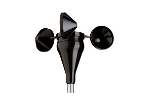
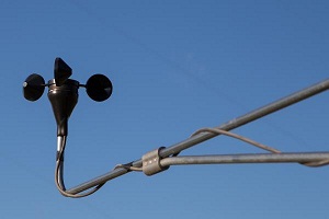
3 Cup Anemometer
|
3 Cup Anemometer
|
|
Applications
|
- Wind turbine control
- Wind speed measurement for programmable controllers
- Wind resource assessment
- Meteorological studies
- Environmental monitoring
|
- Wind turbine control
- Wind speed measurement for programmable controllers
- Wind resource assessment
- Meteorological studies
- Environmental monitoring
|
|
Sensor range
|
1 m/s to 96 m/s (2.2 mph to 215 mph) (highest recorded)
|
1 m/s to 96 m/s (2.2 mph to 215 mph) (highest recorded)
|
|
Instrument compatibility
|
Controllers or loggers requiring a square wave signal
|
Controllers or loggers requiring a square wave signal
|
|
Output signal
|
|
Signal type
|
- Square wave signal from open collector transistor
- External pull-up resistor required
- Frequency proportional to wind speed
|
- Square wave signal from open collector transistor
- External pull-up resistor required
- Frequency proportional to wind speed
|
|
Anemometer Transfer Function
|
m/s = (Hz x 0.765) + 0.35
[ miles per hour = ( Hz x 1.711 ) + 0.78 ]
|
m/s = (Hz x 0.765) + 0.35
[ miles per hour = ( Hz x 1.711 ) + 0.78 ]
|
|
Recommended load resistance
|
- output sinks up to 20 mA
- 3300 Ohm typical pull-up resistor for 24 V
- 1500 Ohm typical pull-up resistor for 12 V
- 330 Ohm typical pull-up resistor for 5 V
|
- output sinks up to 20 mA
- 3300 Ohm typical pull-up resistor for 24 V
- 1500 Ohm typical pull-up resistor for 12 V
- 330 Ohm typical pull-up resistor for 5 V
|
|
Calibration
|
Calibration certificate for #2551 available via electronic download
|
Calibration certificate for #2551 available via electronic download
|
|
Output signal range
|
0 Hz to 125 Hz
|
0 Hz to 125 Hz
|
|
Response characteristics
|
|
Threshold
|
0.78 m/s (1.75 miles per hour)
|
0.78 m/s (1.75 miles per hour)
|
|
Distance constant (63% recovery)
|
3.0 m (10 feet)
|
3.0 m (10 feet)
|
|
Moment of inertia
|
68 x 10-6S-ft2
|
68 x 10-6S-ft2
|
|
Swept diameter of rotor
|
190 mm (7.5 inches)
|
190 mm (7.5 inches)
|
|
Power requirements
|
|
Supply voltage
|
5 V to 26 V DC
|
5 V to 26 V DC
|
|
Supply current
|
9 mA maximum
|
9 mA maximum
|
|
Installation
|
|
Mounting
|
Onto a 13 mm (0.5 inch) diameter mast with cotter pin and set screw
|
Onto a 13 mm (0.5 inch) diameter mast with cotter pin and set screw
|
|
Tools required
|
0.25 inch nut driver, petroleum jelly, electrical tape
|
0.25 inch nut driver, petroleum jelly, electrical tape
|
|
Accessories
|
Protective PVC sensor terminal boot included
|
Protective PVC sensor terminal boot included
|
|
Environmental
|
|
Operating temperature range
|
-55 °C to 60 °C (-67 °F to 150 °F)
|
-55 °C to 60 °C (-67 °F to 150 °F)
|
|
Operating humidity range
|
0 to 100% RH
|
0 to 100% RH
|
|
Physical
|
|
Connections
|
4-40 brass hex nut / stud terminals
|
4-40 brass hex nut / stud terminals
|
|
Weight
|
0.14 kg (0.3 pounds)
|
0.14 kg (0.3 pounds)
|
|
Dimensions
|
- 3 cups of conical cross-section, 51 mm (2 inches) dia.
- 81 mm (3.2 inches) overall assembly height
|
- 3 cups of conical cross-section, 51 mm (2 inches) dia.
- 81 mm (3.2 inches) overall assembly height
|
|
Materials
|
|
Cups
|
One piece injection-molded black polycarbonate
|
One piece injection-molded black polycarbonate
|
|
Body
|
Black ABS plastic
|
Black ABS plastic
|
|
Shaft
|
Beryllium copper, fully hardened
|
Beryllium copper, fully hardened
|
|
Bearing
|
Modified Teflon, self-lubricating
|
Modified Teflon, self-lubricating
|
|
Boot
|
Protective PVC sensor terminal boot included
|
Protective PVC sensor terminal boot included
|
|
Terminals
|
- Brass terminal studs
- Nickel plated brass nuts
|
- Brass terminal studs
- Nickel plated brass nuts
|